S-parameters, also known as scattering parameters and often displayed in an S-matrix, play a crucial role in characterizing and designing complex RF circuits. In this article, we'll explore the basics of S-parameters, their characteristics, functions, and the principles used to implement them, highlighting their importance for efficient and effective port modeling and system design.
S-Parameters Basics
S-parameters, short for scattering parameters, are numerical values that describe the electrical behavior of a linear, time-invariant, multi-port network, such as an RF circuit or system. These parameters quantify the relationship between the incident and reflected waves at each network port. In simpler terms, S-parameters provide a comprehensive understanding of how energy is transferred between different ports within a system.
S-parameters are typically represented in an S-matrix, which is an N x N matrix, where N represents the number of ports in the network. For a two-port network, the S-matrix would be a 2×2 matrix; for a three-port network, it would be a 3×3 matrix. Each element of the S-matrix corresponds to a specific S-parameter, and together, they provide a detailed description of the network's behavior.
Characteristics of S-Parameters
S-parameters are frequency-dependent and are complex numbers, meaning they have both magnitude and phase components.
S-parameters are inherently reciprocal. This property implies that the S-parameters are the same when measuring the response from Port A to Port B or from Port B to Port A.
Importance of S-Parameters
Engineers use S-parameters to design and optimize complex RF systems. By analyzing the S-parameters of individual components, they can ensure that all system elements work together efficiently and effectively. S-parameters are fundamental in creating mathematical models for RF systems. Incorporating S-parameters into system models allows engineers to predict and optimize system performance, identify and mitigate potential signal integrity issues, and troubleshoot problems when they arise.
S-parameters characterize the behavior of many electronic systems, including the following:
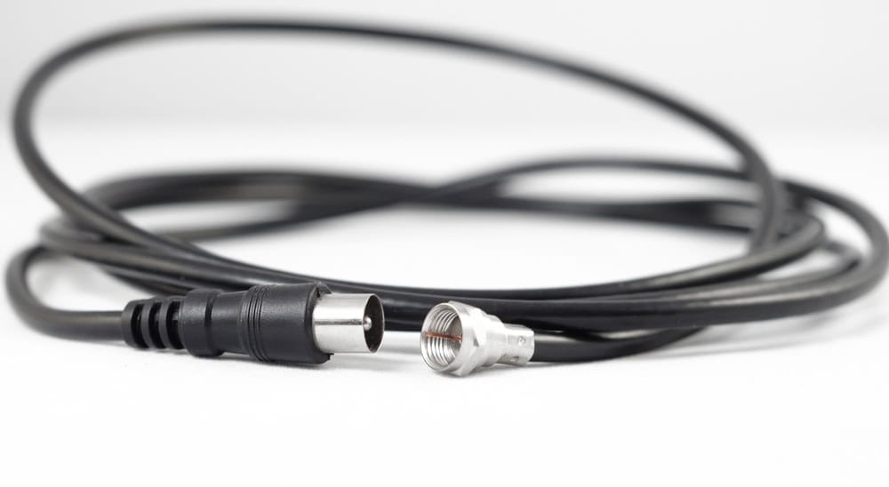
S-parameters are used to characterize and model signal transmission between various components, such as connectors, cables, and waveguides. S-parameters help engineers understand signal reflections, losses, and impedance matching, ensuring efficient energy transfer in high-frequency systems.
In antenna design, S-parameters help evaluate the performance of antennas, assess their impedance matching with the transmission line, and understand how efficiently they radiate or receive electromagnetic waves. Engineers use S-parameters to optimize antenna designs and ensure desired radiation patterns.
S-parameters are crucial for amplifier characterization. By using S-parameters, engineers can determine gain, bandwidth, input/output impedance matching, and stability of amplifiers. This information is crucial for designing and implementing amplification stages in communication systems.
Filters, whether low-pass, high-pass, band-pass, or band-stop, can be analyzed using S-parameters. These parameters help engineers assess how filters affect signal transmission, including insertion loss, return loss, and bandwidth.
Explaining the S-Matrix Structure
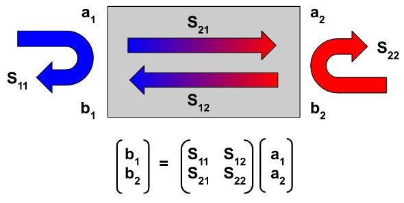
The connections between different components can be represented as two-port networks featuring two incident waves, designated as a1 and a2, at ports one and two, as illustrated in the diagram. The corresponding reflected waves at ports one and two are denoted as b1 and b2. These incident and reflected waves are typically normalized using the characteristic impedance value. The general S-parameters for a two-port transmission line model can be expressed as shown in the equation below the diagram.
When reading the S-parameters matrix, S11 is the S-parameter describing the relationship between port 1 (incident) and port 1 (reflected), S21 between port 2 (incident) and port 1 (reflected), and so on. The S-parameters are determined by measuring the incident and reflected waves at different ports of the network at a range of frequencies. The S-matrix is constructed based on these measurements. The mathematical representation of S-parameters for a two-port network is as follows:
S11 = (b1/a1) when a2 = 0
S12 = (b1/a2) when a1 = 0
S21 = (b2/a1) when a2 = 0
S22 = (b2/a2) when a1 = 0
Here, a1 and a2 represent the incident waves, and b1 and b2 represent the reflected waves. For example, when the incident wave at port one and the output are matched, there are no reflections in the two-port network, so a2 becomes zero. The S11 parameter becomes the input reflection coefficient, S12 is the reverse transmission coefficient (from port two to port one)
S21 is the forward transmission coefficient (from port one to port two), and S22 is the output reflection coefficient.
S-Parameters Physical Implementation and Measurement
In the case of simple two-port systems, S-parameters can be simulated or calculated by hand or using a set of formulas. In a fully realized system, engineers use specialized equipment such as vector network analyzers (VNAs) to send and receive signals at various frequencies to calculate the S-parameters of the system.
Before measurements are taken, the VNA and the test setup must be calibrated (oftentimes with a short, 50-ohm impedance and an open-circuit) to remove systematic errors, ensuring accurate results.
To ensure accurate measurements, it's essential to terminate all unused ports with appropriate impedance loads.
The VNA then sweeps through a range of frequencies, measuring the magnitude and phase of the signals at each port. This data is used to populate the S-matrix.
After measurements are taken, the data is analyzed to determine the S-parameters. Software tools and algorithms are often employed to process the raw data and extract meaningful information.
If you're looking to leverage the power of S-parameters for more efficient and effective system design in your RF and electrical engineering projects, EMA Design Automation is here to assist you.
EMA Design Automation is a leading provider of the resources that engineers rely on to accelerate innovation. We provide solutions that include PCB design and analysis packages, custom integration software, and engineering expertise, which enable you to create more efficiently. For more information on S-parameters basics and how we can help you or your team innovate faster, contact us.