Signal integrity for serial link interfaces is crucial in high-speeds designs. With fast switching speeds, these signals can be easily influenced by adjacent nets altering the value and desired functionality. With SI Metrics Checking in Sigrity, coupled lines typical in serial link interfaces can be quickly analyzed, incorporating crosstalk effects of traces and vias, to guarantee signal performance and intended circuit functionality.
This how-to will provide step-by-step instructions on how to use the SRC – SI Metrics Check in Sigrity to analyze the signal integrity of coupled for Serial Link Interfaces.
To follow along with this tutorial, use the provided demonstration files above the table of contents.
How-To Video
Opening Sigrity for Serial Link Analysis
Step 1: Open Sigrity Layout Workbench or any Sigrity software package and select File > Switch Workflow from the menu.
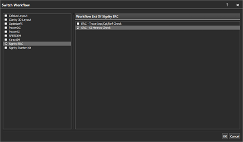
Step 2: From the tool selection list, select a software package that includes Signal Integrity Metric Checking such as Sigrity ERC or Sigrity Starter Kit. In the Workflow list, select SRC – SI Metrics Check and click OK.
Preparing the Design for Simulation
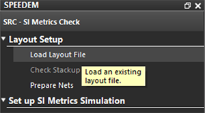
Step 3: Under Layout Setup in the workflow pane, select Load Layout File.
Step 4: Select the SerialLink_SIMetrics.spd included in the design files and click Open.
Note: By default, Enable SI Metrics Check Mode is activated.
Configuring Crosstalk Analysis
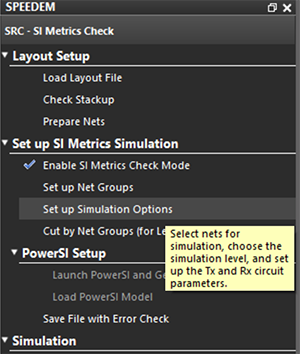
Step 5: In the workflow, select Setup Simulation Options.
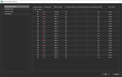
Step 6: In the Setup Simulation Options dialog box, select Net/RX/Pulse Options and ensure all nets are selected.
Note: Within the Net/RX/Pulse Options, you can define the receiver and set up the pulse direction.
Step 7: In the Setup Simulation Options dialog box, select Simulation Level.
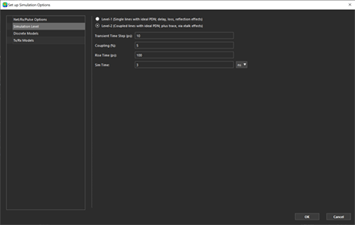
Step 8: Select Level-2 (Coupled lines with ideal PDN; plus trace, via xtalk effects).
Step 9: Set the following Simulation Options:
- Transient Time Step (ps): 10
- Coupling (%): 5
- Rise Time (ps): 100
- Sim Time: 3 ns
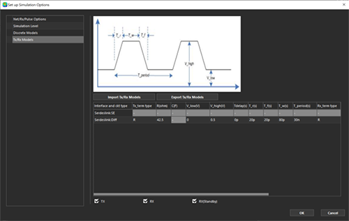
Step 10: In the Setup Simulation Options dialog box, select TX/RX models.
Step 11: Configure the following information for Serdeslink::Diff:
- TX_term Type: R
- R(Ohm): 42.5
- V_low(V): 0
- V_high(V): 0.5
- Tdelay(s): 0p
- T_R(s): 20p
- T_f(s): 20p
- T_w(s): 80p
- T_period(s): 30n
- Rx_term Type: R
Note: The following information can be configured:
- Tx_Term and Rx_Term: Select the termination type for the transmitter and receiver. Select from either, R, Parallel RC, or Series RC. By default, R is selected.
- V_low: Low Input Voltage
- V_high: High Input Voltage
- T_delay: Delay Time
- T_r: Rise Time
- T_f: Fall Time
- T_w: Pulse Width
- T_period: Period Time
Step 12: Select OK.
Running a Crosstalk Simulation
Step 13: In the SRC – SI Metrics Check workflow, select Save File with Error Check.
Step 14: Select Start Simulation.
Note: During simulation, the status is reported as busy and the progress of the simulation is shown. When the simulation is completed, the Results and Report options are automatically enabled.
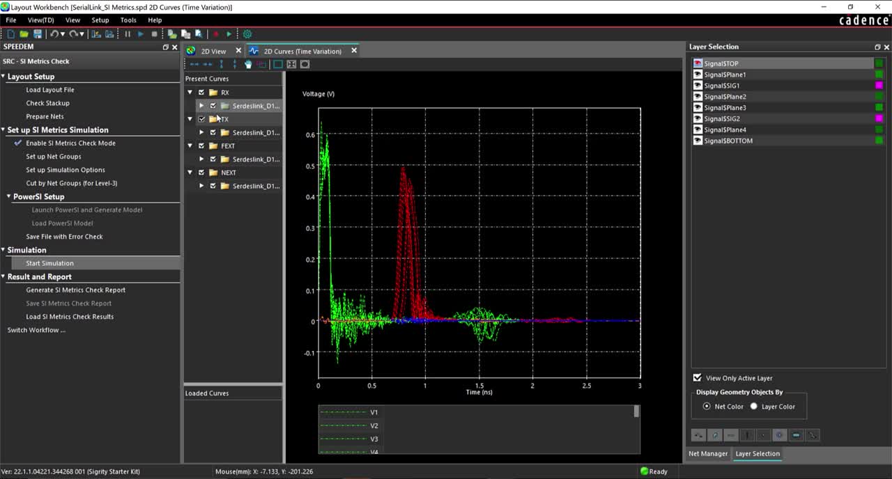
Viewing Crosstalk Results and Reports
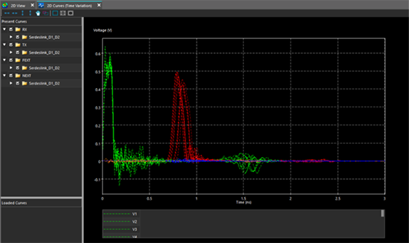
Step 15: View the graphical results. Select the check mark to view the waveforms for the desired nets.
Step 16:In the workflow, select Generate SI Metrics Check Report.
Step 17: Select OK.
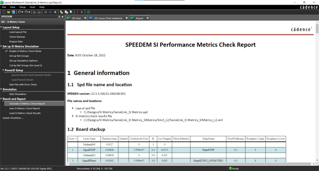
Step 18: View the SI Metrics Check Report.
Note: The SI Metrics Check Report has been generated and includes general information, layout SI Metrics Check net groups, Time-domain simulation options and resources, and SI Metrics Check results.
Wrap Up & Next Steps
Analyze signal integrity for serial link interfaces and guarantee proper circuit functionality with the SI Metrics Check in Sigrity. Get a free trial of Sigrity and enroll in our Sigrity workshops to learn more about Signal Integrity Metrics, Electrical Rule Checking, IR Drop Analysis, Return Path Analysis, and more to improve signal and power integrity in your designs.
