To reduce costs, it’s common to design a single PCB that can accommodate varying functionality or design requirements based on model features and where the product is being sold; however, keeping track of modified component values and requirements in a core design can be complicated. Easily define and manage variant components with OrCAD Capture CIS.
This how-to provides step-by-step instructions on how to define a variant design containing do not stuff components and components with varying values.
How-To Video
Creating a Variant
Step 1: Open a design in OrCAD Capture CIS 17.4.
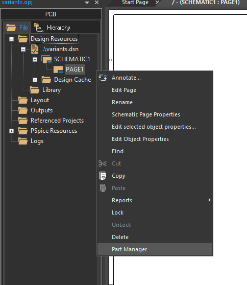
Step 2: Right-click on a schematic page and select Part Manager.
Note: This will open the Part Manager Tab.
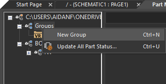
Step 3: In the Part Manager tab, right-click on Groups and select New Group.
Step 4: Add Variant 1 as the name and click OK.
Define Do Not Stuff Components
Step 5: Back in the schematic, select the components which will differ in the variant design.
Note: Hold down the CTRL key to select multiple components.
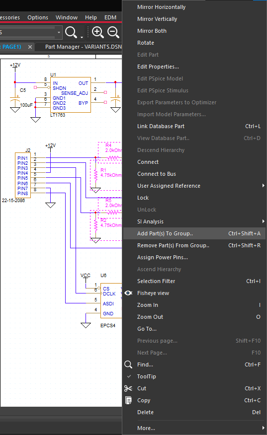
Step 6: Right-click and select Add Part(s) to Group.
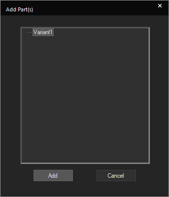
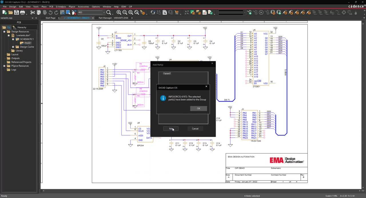
Step 7: In the Add Part(s) window, select group Variant1 and click Add. Click OK.
Step 8: Back in the part manager, select Variant1 under Groups.
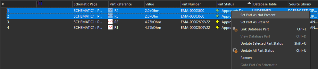
Step 9: Select the components that should not be included in the variant design. Right-click and select Set Part As Not Present.
Note: Components have been flagged with a red ‘X’ and identified as “Do Not Stuff”.
Define Components with Different Values
Step 10: Select the components with differing values in the variant design. Right-click and select Link Database Part.
Note: If you receive a warning, select Yes to proceed.
Step 11: In the CIS Explorer- Link Database Part tab, select Query.
Step 12: Set the following search criteria:
- Property: Value
- Compare:=
- Value: Desired Component Value (example: 1k)
Step 13: Press Enter.
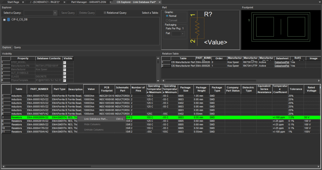
Step 14: Select the desired component for the variant design. Right-click and select Link Database Part.
Note: This will re-open the Part Manager Tab. Differing components are identified with a green check mark and new component information is visible, including part number and value.
Wrap Up & Next Steps
With various models of the same product being sold in multiple countries, it is vital to create a single PCB that can support the required differences to keep costs down. Easily manage component modifications for variant designs with integrated definition and support in OrCAD Capture CIS. For more information and in-depth training on additional features, view our E-Learning and instructor led courses for OrCAD Capture CIS.
