Circuit simulations are often configured with ideal components, a clean and precise voltage input, and clean signals but real-world circuit tests are not ideal. Real components cannot be defined precisely and real voltage sources always contain some form of noise. This slight variation between real and ideal may be enough to distort the expected results and could cause the circuit to not operate correctly. For a comprehensive simulation, easily perform noise analysis and report the top components contributing to noise with PSpice.
This how-to will provide step-by-step instructions to perform noise analysis in OrCAD PSpice to determine how much distortion noise is expected to cause.
To follow along with this tutorial, download the provided files above the table of contents.
How-To Video
Performing an AC Simulation with Noise
Step 1: Open the provided design, NoiseAnalysisExample.dsn, in OrCAD PSpice Designer.
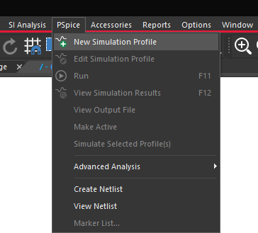
Step 2: Select PSpice > New Simulation Profile from the menu.
Step 3: Name the simulation AC_Noise_Analysis and click Create.
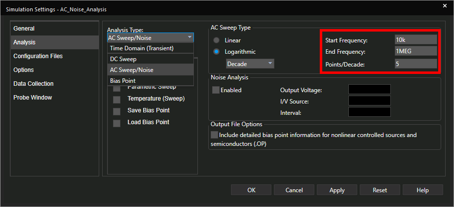
Step 4: Select AC Sweep/Noise from the Analysis Type drop-down menu.
Step 5: Enter 10k for the Start Frequency, 1MEG for the End Frequency, and set the Points/Decade to 5.
Step 6: Select Enabled under Noise Analysis to activate Noise Analysis.
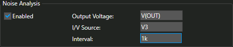
Step 7: Enter V(OUT) for the Output Voltage, V3 for the I/V Source, and 1k for the Interval.
Note: The Output Voltage defines the node where the noise output is measured. The I/V source defines the name of the source where equivalent input noise is calculated. The Interval defines how often the noise analysis data is written to the output file.
Step 8: Click OK to save the settings and close the window.
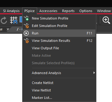
Step 9: Select PSpice > Run from the menu. The PSpice A/D window will open.
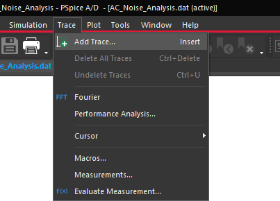
Step 10: To confirm the circuit works as expected, select Trace > Add Trace inthe PSpice A/D window.
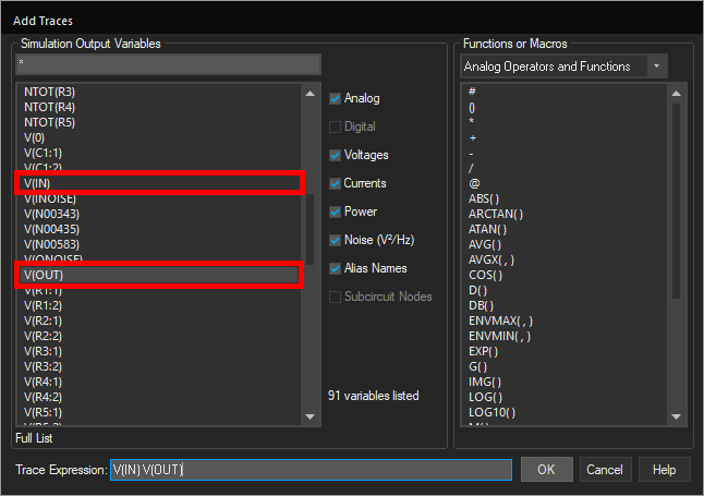
Step 11: Under Simulation Output Variables in the Add Traces window, select V(IN) and V(OUT) and click OK.
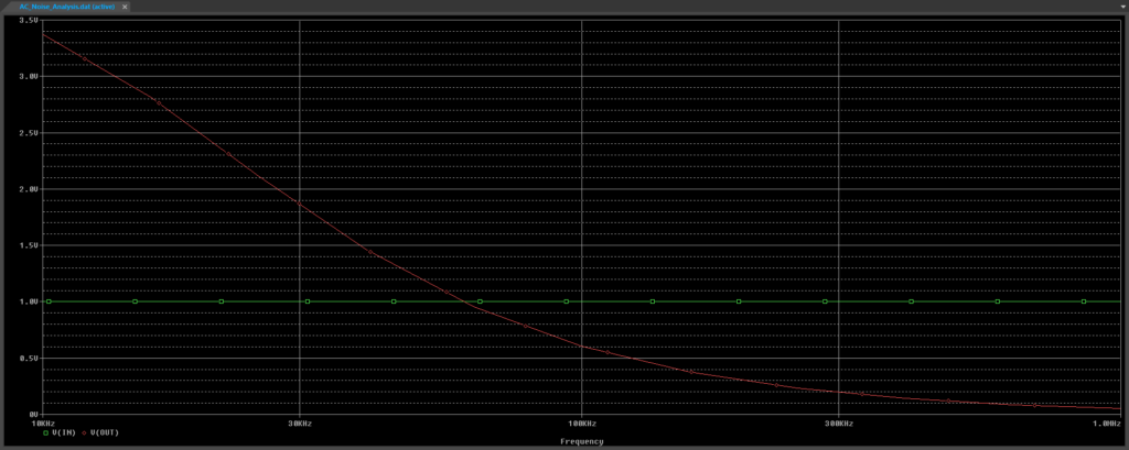
Step 12: View the results. The amplitude of V(IN) is the same across the entire spectrum and the amplitude of V(OUT) decreases as expected.
Step 13: Hold Shift to select both traces in the legend and press Delete on the keyboard to delete the traces.
Viewing Noise Analysis Results
Step 14: Select Trace > Add Trace from the menu.
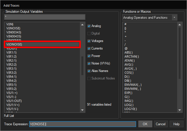
Step 15: Select V(ONOISE) from the Simulation Output Variables list. Click OK.
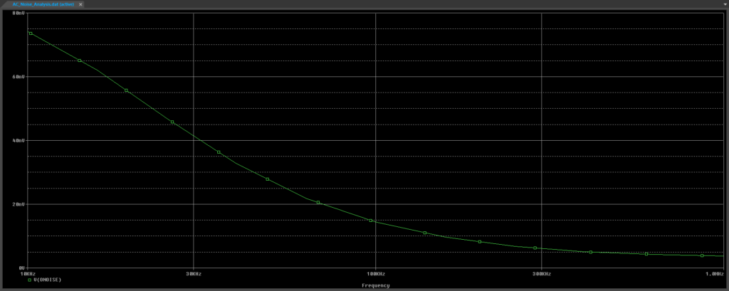
Step 16: View the results. The amplitude of the noise output decreases as well.
Step 17: To examine the signal-to-noise ratio of the circuit, double-click the V(ONOISE) trace in the legend.
Step 18: Delete the written expression in the Trace Expression box.
Step 19: Select Analog Operators and Functions from the Functions or Macros dropdown if it is not already selected.
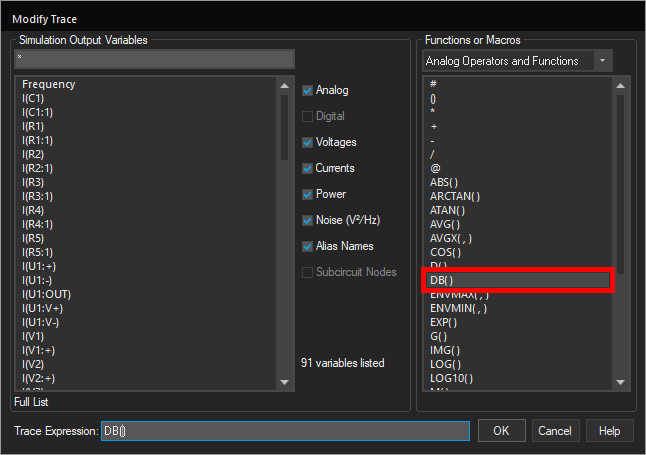
Step 20: Select DB() from the function list. DB() has been added to the Trace Expression box.
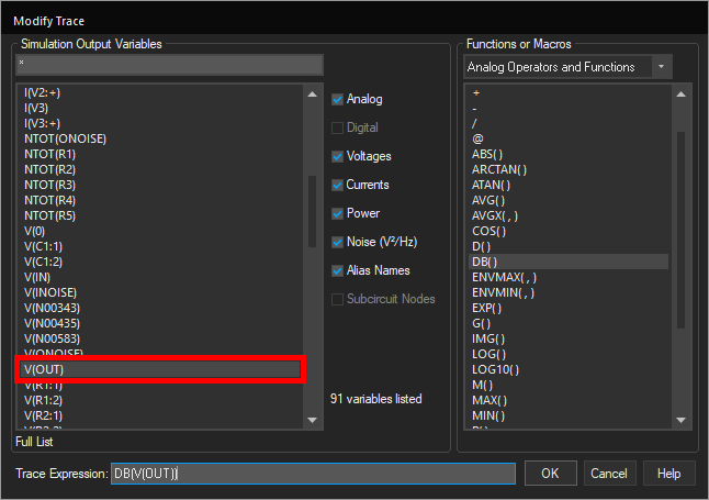
Step 21: Select V(OUT) from the Simulation Output Variables list.
Step 22: Use the keyboard to enter the / character for division (inside the DB parenthesis).
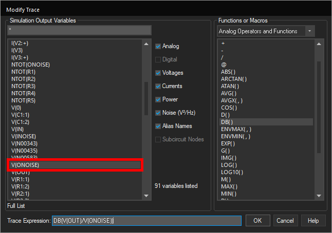
Step 23: Select V(ONOISE) from the Simulation Output Variables list to create the final expression: DB(V(OUT)/V(ONOISE)). Click OK.
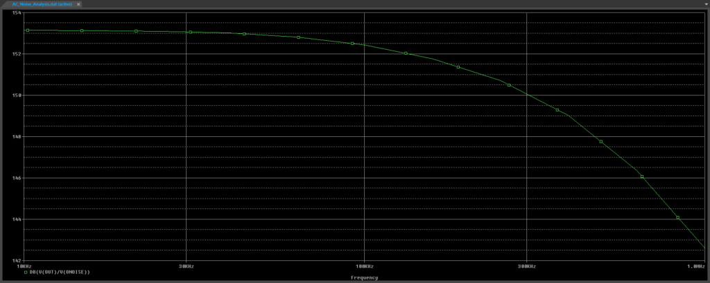
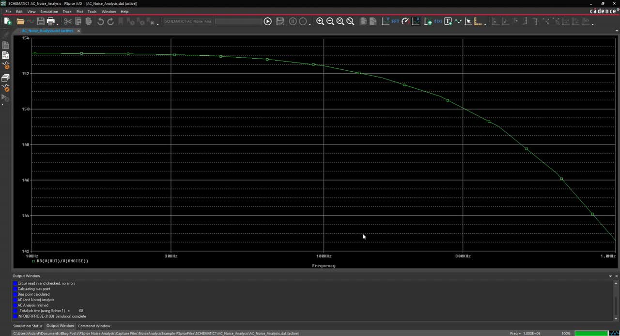
Step 24: View the results. The signal-to-noise ratio peaks at an impressive 153.15dB and stays above 150dB until around 300kHz.
View a Detailed Noise Report
New in OrCAD PSpice 22.1 is the ability to specify how many components are reported when generating a detailed report identifying top contributors to the noise.
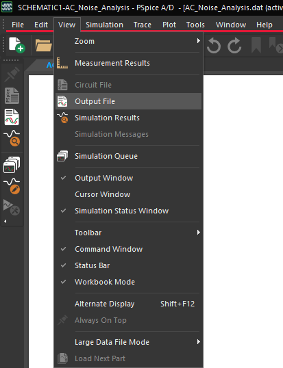
Step 25: Select View > Output File from the menu to open the output file.
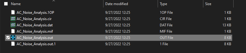
Note: This file is also accessible in the provided materials under NoiseAnalysisExample-PSpiceFiles\SCHEMATIC1\AC_NOISE_ANALYSIS\AC_Noise_Analysis.out.
Step 26: Scroll down to the header ****Top Contributors to Output Noise ***.
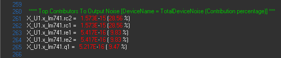
Step 27: View the list of noise-generating components. In this example, 5 top contributors to output noise are reported with U1 generating the bulk of the noise.
Step 28: Close the Output file and return to the schematic.
Adjusting the Number of Top Contributors
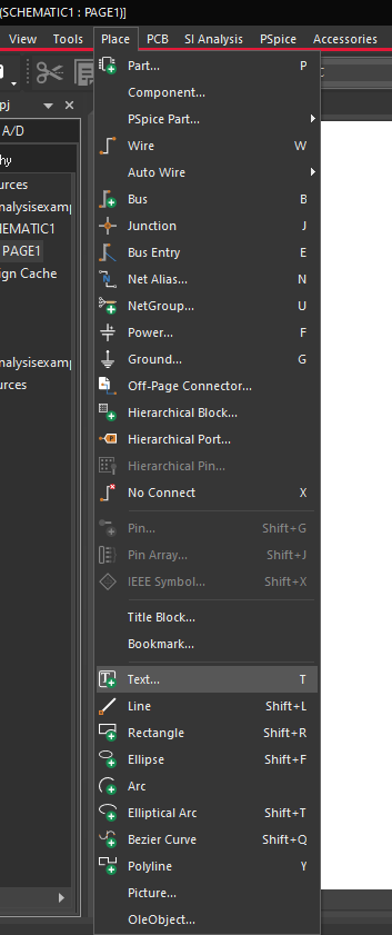
Step 29: Select Place > Text from the menu.
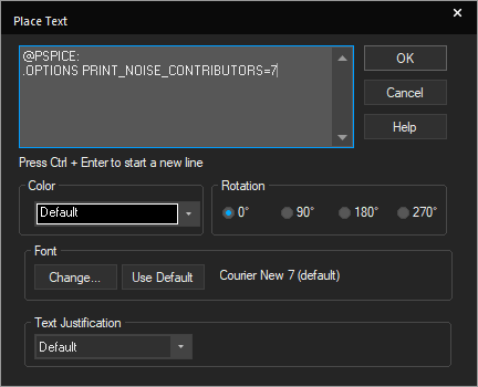
Step 30: Add the following text:
@PSPICE:
.OPTIONS PRINT_NOISE_CONTRIBUTORS=7
Note: To move to the next line, press CTRL + Enter. Change the number in this command to adjust how many top contributors to output noise are reported.
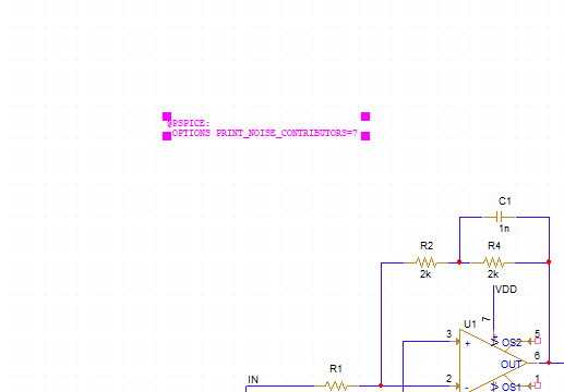
Step 31: Click OK. Click to place the text in the schematic.
Step 32: Select PSpice > Run from the menu. The PSpice A/D window will open.
Step 33: Select View > Output File from the menu to open the output file.
Step 34: Scroll down to the header ****Top Contributors to Output Noise ***.
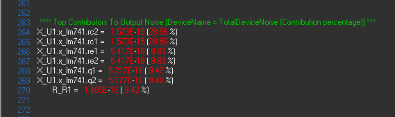
Step 35: View the list of noise-generating components. The list now reports the top 7 contributors to output noise.
Wrap Up & Next Steps
Quickly simulate realistic circuit behavior and analyze the circuit for noise with the Noise Analysis feature and advanced reporting in OrCAD PSpice. See what’s new in 22.1 and upgrade your license today.
