Imagine going through the final stages in delivering your product to market, when you come to find errors in the fabrication or assembly process. You then begin to think of all the things that could have gone wrong: Was it my PCB layout? Was it the materials used? Were my prototypes different from my original manufacturing files? DFM analysis software can help solve these problems. The term “DFM” stands for “Design for Manufacturability.” Similarly, DFA refers to “Design for Assembly” and DFMA, or “Design for Manufacturing and Assembly,” combines these two strategies.
Analysis that checks your design for DFM issues compiles PCB layout topology to reduce problems that can be encountered during the PCB fabrication and assembly stages of the manufacture of an electronic system. Knowing why it is important to follow good DFM guidelines and principles is essential. Otherwise, determining if a problem is manufacturing or design related becomes an expensive guessing game.
But My Manufacturer Handles DFM, That’s Enough Right?
Often design teams look at DFM as a “manufacturing problem” and something handled by their contract manufacturers (CMs) or downstream partners. In fact, many manufacturers will perform DFM analysis prior to production to identify and fix issues. Where this process tends to fall apart is CMs often do not share any changes they made during PCB manufacturing with the design team. This means that changes may be made without a full understanding of the design and its performance or electrical requirements.
The results can be devastating when a design team then sends what they think are the specs for the previously manufactured board off for a new revision, a new production line, or second manufacturing partner, only to realize the PCB fails in some, most, or all of the finished devices. Performing your own analysis based on sound DFM principles and the DFM guidelines from your CM prior to the prototype could have detected those same issues, allowing you to incorporate the changes into the PCB design where they belong. Doing so would have lowered the cost, maintained design intent, and ensured follow-on builds also work correctly.
How To Best Incorporate DFM Guidelines Into Your Design
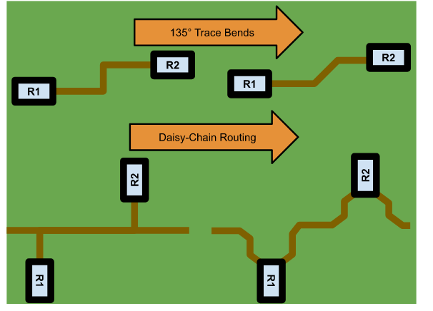
With DFM software, you can detect errors that would normally go undetected and result in the rework of the design, or a total scrap of the product. The most typical DFM issues that pass detection in the CAD system, but result in PCB failures when manufacturing are: starved thermals, acid traps, slivers, insufficient annular ring, along with a few others. Having the capability to perform DFM, DFA and/or DFMA analysis in your PCBA design software is the best way to detect these errors.
Industry leading ECAD software program, OrCAD PCB Designer, integrates DFM checking along with many other design features. Some capabilities include automatic configuration of rules based on manufacturer specifications as well as real-time checks for fabrication, assembly, and testing to identify and resolve common DFM issues when change is easiest. These capabilities can help reduce scrap, increase yield, and prevent costly time to market setbacks.
For more information on common DFM issues and how to solve them, read this e-book.
EMA Design Automation is a leading provider of the resources that engineers rely on to accelerate innovation. We provide solutions that include PCB design and analysis packages, custom integration software, and engineering expertise, which enable you to create more efficiently. For more information on DFM guidelines and principles and how we can help you or your team innovate faster, contact us.