When test points are incorporated during the PCB layout, it is important to update the schematic for testing, inspection, and debugging purposes. Unclear or inaccurate documentation can result in additional time spent troubleshooting as well as difficulty diagnosing potential issues. Easily add test points from the PCB to the schematic with the Test Point Back Annotation App. The Test Point Back Annotation App allows for automated addition of testpoints to nets in the schematic using a testprep file from OrCAD PCB Designer.
This quick how-to will provide step-by-step instructions on how to quickly generate schematic test points based on the PCB layout with the Test Point Back Annotation App in OrCAD Capture.
To follow along, download the provided files above the table of contents.
How-To Video

Generating a Test Point Report
Step 1: Open the provided design, Testpoint_Back.brd, in OrCAD PCB Designer Professional.
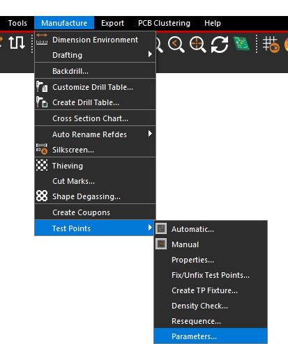
Step 2: Select Manufacture > Test Points > Parameters from the menu to open the Testprep Parameters window.
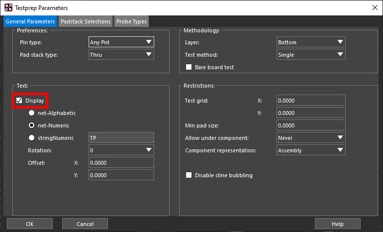
Step 3: Ensure that Display is checked under “Text.” Click OK to close the Testprep Parameters window.
Step 4: Select Export > Reports from the menu to open the Reports window.
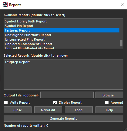
Step 5: Scroll down the list of available reports and double-click Testprep Report to add it to the list.
Step 6: Select Generate Reports.
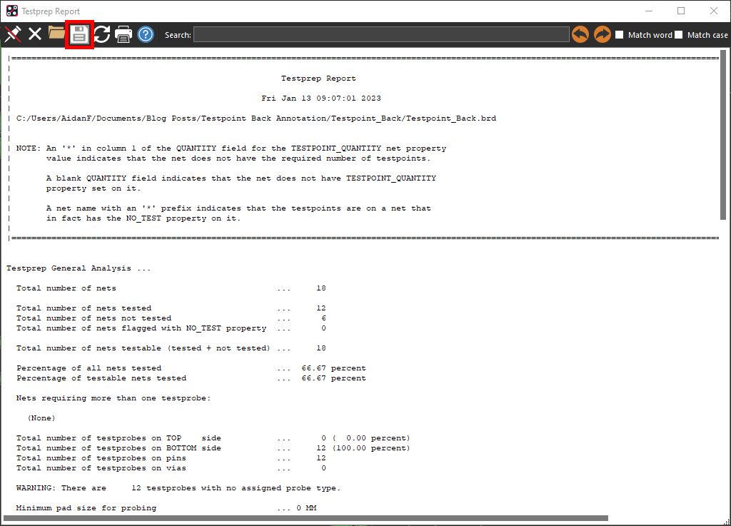
Step 7: The Testprep Report will open directly in PCB Editor. Select the Save icon to save the report.
Step 8: Name the file testpoint_back.rpt. Click Save.
Step 9: Close the report. Select Close in the Reports window.
Loading the Test Point Report
Step 10: Open the provided design, TESTPOINT_BACK.DSN, in OrCAD Capture.
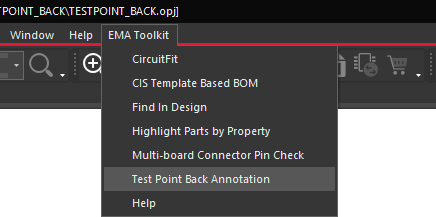
Step 11: Select EMA Toolkit > Test Point Back Annotation from the menu. The Place Test Points window opens.
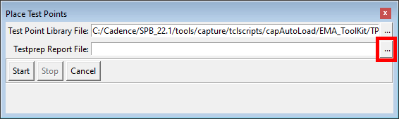
Step 12: Select the ellipsis for Testprep Report File to load the report file.
Step 13: Select the testpoint_back.rpt file and click Open.
Adding Test Points in the Schematic
Step 14: Click Start to run the testpoint annotation. The window will close automatically.
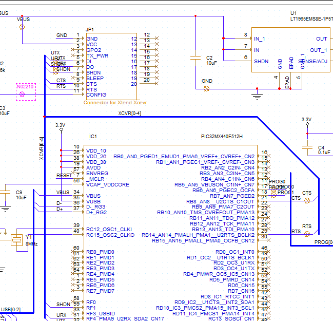
Step 15: Click the individual nets surrounding JP1 and IC1 to generate the test point symbols.
Wrap Up & Next Steps
Quickly add test points in the schematic from a testprep report with the Test Point Back Annotation App in OrCAD Capture. This app and others are part of the EMA Toolkit, one of the benefits of EMA Support +. The EMA Support + program is available to all EMA customers on active support and includes additional benefits and tools to expedite the PCB design process, such as time saving apps, additional training, and more. See what’s included with EMA Support + and learn how to get access to these exclusive benefits.
